
Made to suit your equipment dimensions and operating conditions
Luwint can supply customised cartridge mechanical seals for applications where a standard seal does not meet the installation or operating requirements.
Customisation can include the cartridge sleeve, gland mounting arrangement, installation length, seal-face materials, elastomers and fluid connections. Single, double and cooling/quench configurations can be considered following a review of the application.
The starting point is the equipment drawing and operating duty—particularly the shaft diameter, seal-chamber bore size and usable chamber depth.
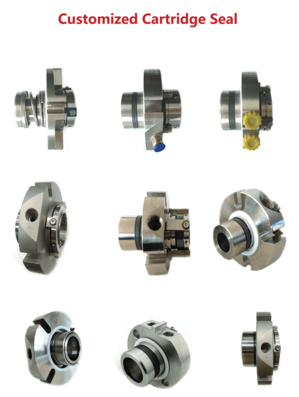
Designed Around Your Installation
Cartridge construction combines the sealing components, sleeve and gland in one assembly. A customised cartridge allows these parts to be configured around the available installation space and the required sealing arrangement.
Depending on the application, customisation may include:
-
Sleeve dimensions to suit the shaft or existing equipment sleeve.
-
Gland dimensions, mounting slots and bolt pattern.
-
Internal insertion length and external cartridge projection.
-
Seal-face combinations and chemically compatible elastomers.
-
Metal components suited to the process liquid.
-
Flush, quench, drain or double-seal support connections.
Final dimensions, materials and operating limits are confirmed for the selected design.
Essential Dimensions: Bore Size and Depth
Seal-chamber bore size is the internal diameter of the chamber surrounding the shaft where the seal enters the pump. It determines the radial space available for the cartridge.
Seal-chamber depth is the axial distance measured inward from the gland mounting face to the chamber bottom, throat bush or other limiting feature. It determines the available insertion space.
For stepped or tapered chambers, provide each diameter and its corresponding depth. Include any internal bush, shoulder or restriction that reduces the usable space.
| Dimension | Information to provide |
|---|---|
| Shaft or sleeve outside diameter | Actual diameter where the cartridge will mount; identify whether it fits over a bare shaft or an existing sleeve |
| Seal-chamber bore diameter | Internal diameter, including steps, tapers and restrictions |
| Usable chamber depth | Distance from the gland mounting face to each internal limiting feature |
| Gland mounting face | Available sealing surface, recess/register diameter and depth, and gasket or O-ring location |
| Mounting bolts or studs | Quantity, diameter or thread, bolt-circle diameter or centre distances, and available stud projection |
| External axial clearance | Distance from the mounting face to the nearest bearing housing, coupling or other obstruction |
| External radial clearance | Space available around the gland, drive collar and pipe connections |
| Shaft features | Positions of shoulders, steps, keyways and threads relative to the mounting face |
Please state whether dimensions are in millimetres or inches. A dimensioned sectional drawing is preferred. Clear photographs and a marked sketch can help us begin the review.
Operating Conditions We Need
| Condition | Details to provide |
|---|---|
| Equipment | Pump manufacturer, model, serial number and horizontal or vertical orientation |
| Process liquid | Liquid name, composition and concentration; supply an SDS where available |
| Liquid properties | Viscosity, specific gravity and vapour pressure at operating temperature, where known |
| Solids | Concentration, particle size and whether particles are abrasive or fibrous |
| Temperature | Normal, minimum and maximum temperatures, including cleaning or steaming cycles |
| Pressure | Normal and maximum seal-chamber pressure, including start-up, shutdown, vacuum or pressure reversals |
| Speed and rotation | Operating RPM, variable-speed range and rotation direction with the viewing position stated |
| Operating cycle | Continuous or intermittent operation, starts and stops, and known loss-of-prime or dry-running events |
| Existing seal performance | Current seal type, materials, leakage, service life and observed failure symptoms |
| Process requirements | Permitted leakage, sensitivity to dilution, and any material or certification requirements |
Please identify whether pressures are gauge or absolute. If seal-chamber pressure is unknown, provide suction and discharge pressures together with the pump details for assessment.
Flush, Cooling and Double-Seal Support
Tell us what services are available: flush liquid, cooling water, quench medium or a barrier/buffer-fluid system. Include the available pressure, temperature, flow rate, fluid quality and connection details.
For double cartridges, also describe the existing reservoir or circulation system and whether supporting fluid may enter the process. Seal design and support-system requirements must be assessed together.
Request a Custom Cartridge Seal
Send your drawings, measurements, photographs and operating information to Luwint. Include the required quantity and preferred delivery date.
If you do not have every detail, start with the pump model, shaft diameter, chamber bore, chamber depth and operating duty. We can identify the remaining information needed to assess the design.
Contact us for a customised proposal, dimensional drawing, pricing and lead time.
Wayne Liao
Email: wayne@luwintonline.com
Phone: 0433 986 633